Circuit Analysis : the Boss BD2
From gritty boosts to heavy punk distorsion. I can't figure out a way to use it for blues.
From gritty boosts to heavy punk distorsion. I can't figure out a way to use it for blues.
Hello everyone, welcome to our first circuit analysis, let's explore the Boss BD2 ! This pedal was released in 1995 and was a huge success until today. Designed to produce "tube like" distorsion - as 90% of the ODs on the market anyway - this pedal is my favorite dirty boost. Clearly, it is a hot rodded overdrive, which is in my opinion incredibly versatile while having its own personnality. It is also one of the most responsive pedal I have tested yet, driving the attacks of the note when playing. In this article, I want to show you the guts of this circuit, so that you can mod it if you want, for example. The original schematic can be found on Experimentalists Anonymous website, but I will not use it for the sake of simplification.
Boss uses JFETs transistors for its buffered bypass. I will not describe this, only the effect circuit. Electrosmash.com has a perfect explanation for this type of switching, and I suggest that you read it here if you are interested. The schematic I present here won't show the JFET switching, but includes the buffers it needs. Let's examine the power supply first.
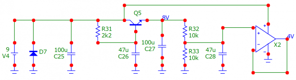
The 9V input for the battery or the Boss power supply appears on the left. D7 is a reverse-biased diode used for polarity protection, it will almost short-circuit the power supply if it has the wrong polarity. C25 filters the possible noise on the power supply. The combination of R31, C26 and Q5 forms a capacitance multiplier. The transistor Q5 makes the capacitor C26 look like if it was (hfe+1) times larger, where hfe is the current gain of the transistor. This circuit provides heavy voltage noise filtering to get the cleanest voltage possible for the audio circuit. However, the transistor also loses about 1V of available voltage, and only provides 8V to the circuit. C27 filters the noise it even more. The voltage divider formed by R32 and R33 generates a 4V reference voltage, fitlered by C28. The output opamp buffers the reference voltage and provides a way to get more current while keeping the voltage stable. This power supply should really be quiet after all these stages of filtering !
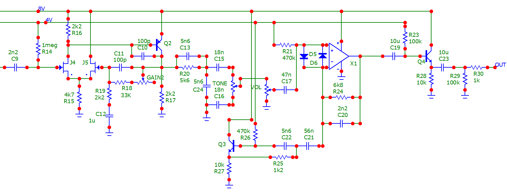
Let's now examine the audio circuit there, it is a quite complex circuit, nowhere near other guitar pedals in fact ! The whole schematic will be split to analyse each section more easily.
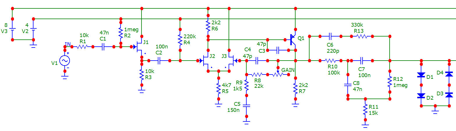
Here is the first part of the schematic. The guitar signal passes to a JFET buffer with unity gain. C1 forms a high-pass filter with the biasing resistor R2. Voltage gain of this circuit is almost one, but it has a high input impedance, perfect for a guitar, while having a really low output impedance to drive the following gain stage. R4 provides bias to the JFET J2. J2 and J3 forms a differential pair, and together with Q1, a basic operationnal amplifier in fact ! The output signal goes through a negative feedback network composed of the first gang of the gain pot, R8, R9, C4 and C5. When you increase gain, the total resistance from Q1 collector to R9 increases, so less negative feedback is applied, leading to more gain out of the whole gain stage. C4 and C3 are used to stabilize the opamp to prevent oscillation.
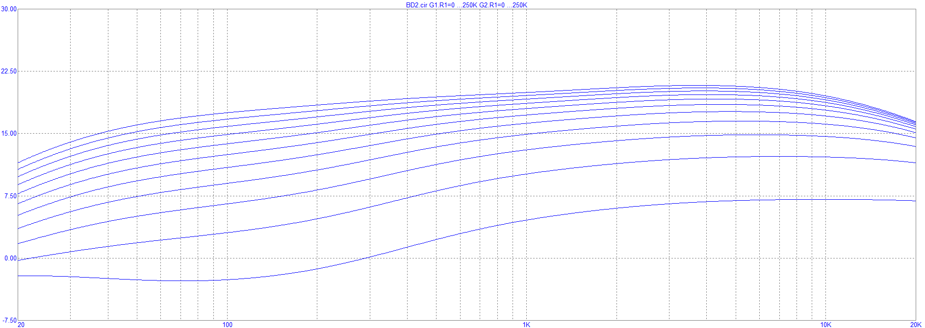
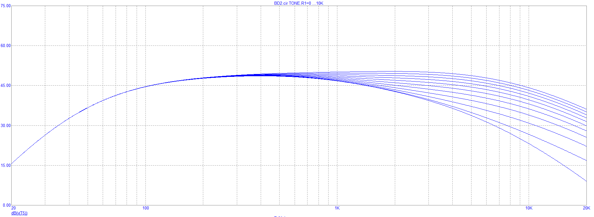
Here is the frequency response of the buffer and opamp gain stage when varying the gain potentiometer.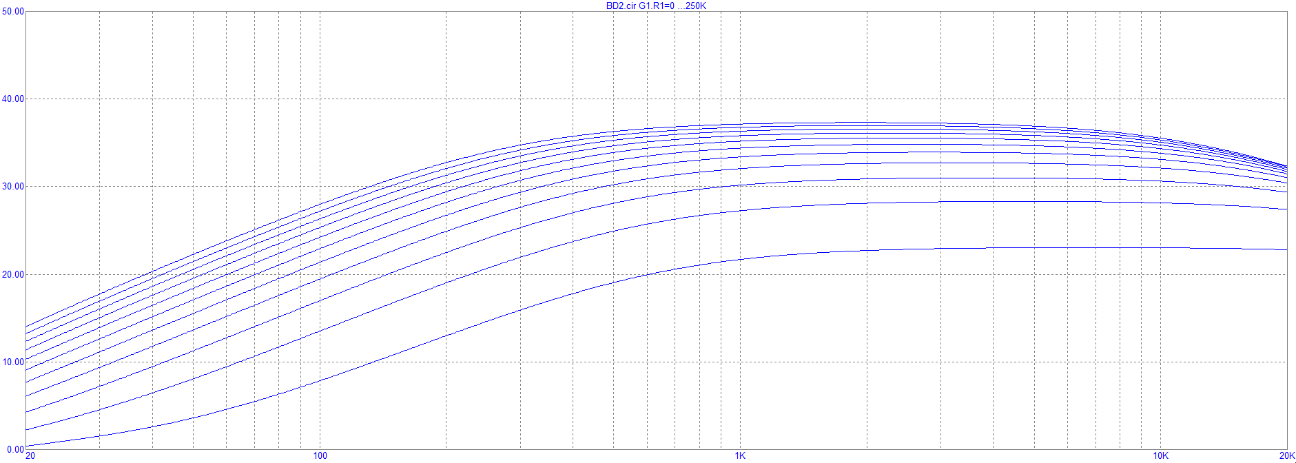
The next stage is a network of resistors and capacitors... Which is in fact a guitar amp tone stack with fixed Treble, Mid and Bass controls. Here, Bass is maxed out, while Mid and Treble are kept at their minimum value. Lowering R12 will lead to less bass frequencies, while taking the output signal from the other leg of R13 will lead to maximum treble - which the stock pedal really doesn't need ! You can also increase the mid frequencies by increasing R11. Or replace R11, R12 and R3 by potentiometers to get a full pre-saturation tone stack. Here is that circuit frequency response.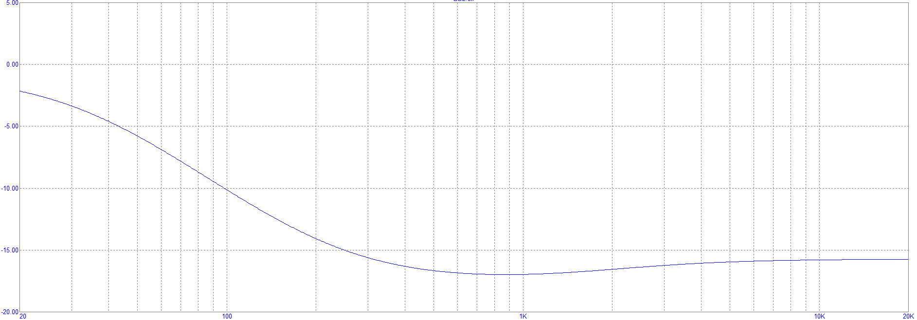
And now, the whole frequency response from input to that point. Gain is maxed out, and we can understand now why we can get a harsh, trebly sound out of this circuit. The Tone stack has a low input impedance, which loads the opamp gain stage. This explains why we get such variations on the frequency response, and even with max bass, we still have more highs !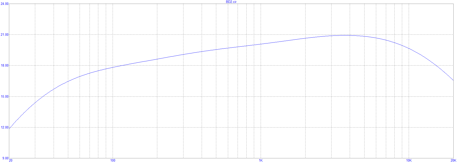
The diodes limits the output level and clip the signal. You can get harder clipping by having only one pair of back-to-back diodes, or replace them by LEDs or any combination for asymetrical clipping for example. Now, the signal goes through the other part of the circuit.
Yet again, the signal goes through the exact same opamp gain stage with the second gang of the gain pot. Both GAIN1 and GAIN2 potentiometers share the same axis, so both move at the same time when you turn the gain knob. Because you have so much gain on this pedal, most of the hard clipping occuring in fact comes from the opamps not being able to go higher than 8V or lower than 0 - hence saturating and generating a lot of harmonics. At lower gain, the first stage diodes will clip smoothly. Because of this characteristics though, the pedal is said to be dynamic, because if the input signal is not high enough, it can go through the entire pedal with minimum distorsion. However, when having a larger signal, the circuit immediately clips, because of both the diodes and the discrete opamp stages. Clipping occurs at different points, exactly like a tube amp - but doesn't sound nowhere near though. Here is the frequency response with the dual-ganged going from low to high, as well as the clipping waveforms. The blue sine wave provided is the 50mV amplitude signal sent at the input.
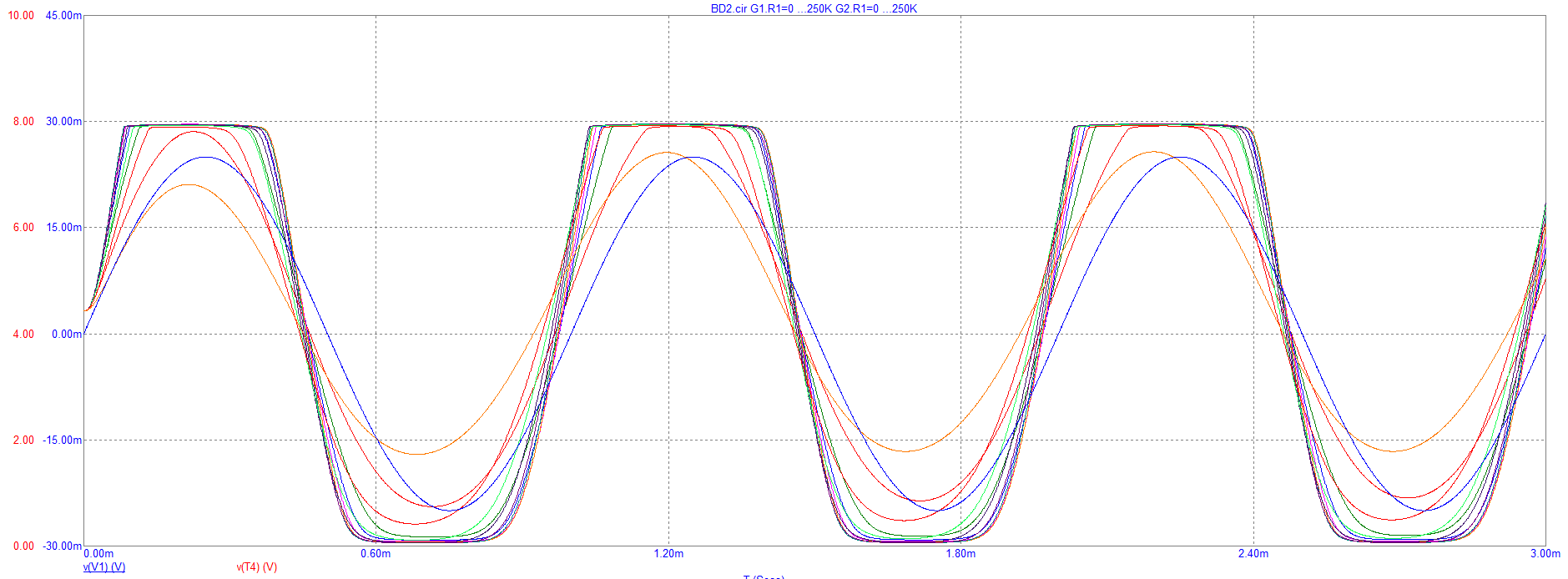
Yup, it really goes to a square waveform ! Anyway, the following resistors and capacitors form a low-pass filter for the tone control, followed by a volume pot. The tone changes the shape of the waveform by smoothing the edges of the signal when it is rolled off. With max gain, here are the frequency response and the waveformes again, when varying the tone pot.
![]()
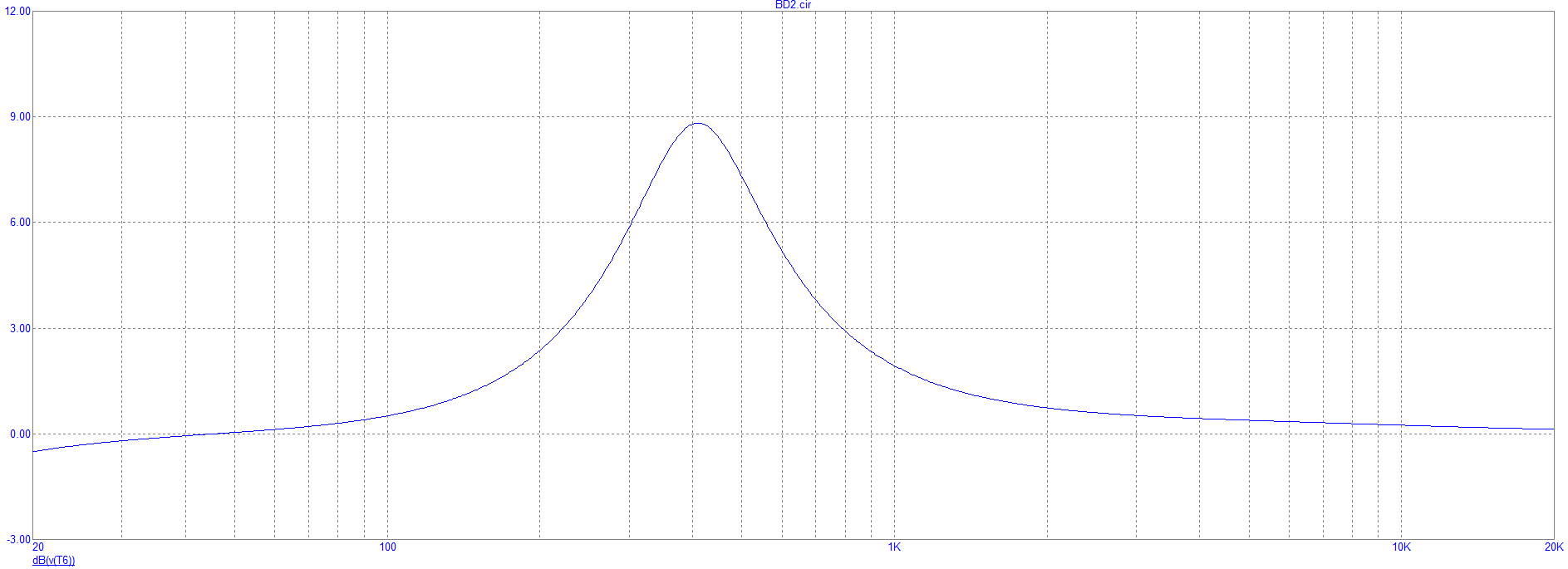
The following gain stage is an active peak filter driven by the opamp IC. Diodes D5 and D6 provide input protection to prevent clipping of the opamp. The weird transistor circuit is called a gyrator and turns capacitor C22 into a "virtual inductance" of value C22*R26*R25, which is about 3H in this case, with a 1k2 series resistance. That simulated inductor forms a notch filter with C21, but because this is placed in the feedback loop of the opamp, it will ask the opamp for more output voltage around those frequencies. This is a peak filter ! Here is its frequency response.
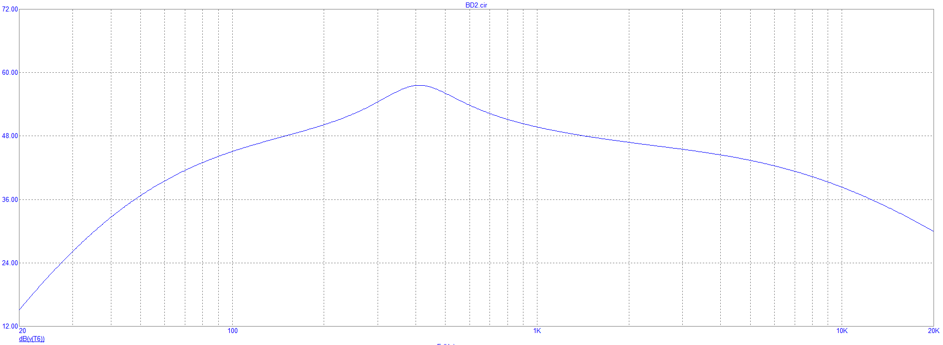
The last transistor of this circuit is an emitter follower, buffering the signal for low output impedance. The total frequency response of the pedal with 50% tone and maximum gain is shown here. We definitely see the impact of the peak filter. By changing C21, C22, R25 and R26, you can shape the peak filter to change its frequency or its width.
And here it is, we traced down the whole signal path and circuitry of that pedal - with no maths equations at all ! By looking at structures only, you can understand where the signal goes, and what the components do as well. Then, you can change their value to alter the tone and saturation of the pedal, or even simulate it in a software to visualize the changes as we did today. I am using Microcap 12, which is now free, and works pretty well I must say !
The Boss BD2 is definitely one of the most capricious Boss pedal I've ever played. Not the most transparent overdrive out there, it has its own character, and by looking at the circuit we know understand why. Nothing like the simpler Ibanez Tube Screamer or MXR Distorsion +, the BD2 uses a combination of discrete JFET opamps and complex filters tone generate that dynamic distorsion, until you max out the gain for total fuzzyness !
Hi! thank you for your article! it's very interesting. I notice that on my BD-2 the cap C22 of the pass band filter is not 5.6n as showed in the schematics but 56n, tha same of the other cap C21. this will change everyting on the peak, it is at 119 Hz instead of 378 Hz. what do you think, could you check on your pedal?
Best regards,
Michele
Yes, C21 and C22 (originally C9 and C16 in BD-2) have 56nF, it means the peak is around 100Hz (it's a post-gain bass boost).
A million thanks for this exhaustive yet simple to follow explanation of the circuit. I love your comments of what possible change in components would do to the tone and the graphs with the waveforms and freq responses are so nice and complement the flow in your explanations so well!
Brilliant!!
Uhmmm..? But all info about this pedal is more complex... Add in here the mind in a BD-2 is a special touch from a IC for tube "extreme sound quality". The Magic IC NE645B from Dolby Laboratories. IC Noise reduction..!
Hi
very nice analysis !
actually I would like to try modding the stock BD2 to transform it in a distortion pedal. I actually like it a lot with the gain maxed but it gets too noisy. would like to add a simple switch that maximase the gain capability whitout adding too much noise. do you think its possible ? could you point out some mods ?
Thanks
Interesting article. I notice that the gain control in your schematic has one end floating, the actual circuit does not, it is connected to the wiper. I would disagree with your assessment that the BD-2 is not transparent, the overall frequency response is quite flat, except for a bit of roll-off below 100Hz and a bump at 130Hz and IMO is quite transparent, unlike the Tube Screamer with its mid-frequency hump. What gives this pedal a little harshness is not necessarily the internal frequency responses per se, but the inter-stage clipping. At lower clipping levels, the back-to-back diodes are dominant, yielding pleasing 2nd order harmonics. At higher gain settings, 3rd-order harmonics are added, which would add some harshness, but only starting at the 7th harmonic.
Hello!
I am a student in a preparatory class in France (classe de PCSI au lycée ENCPB Paris) and I would love you guys to do the same in depth analysis but of the BOSS_DS_2 because I have an oral, a TIPE as we say, on the subject.
Thank your for your understanding,
Cordially,
Hemal KRISHNA Paris France
What if you un-ganged the drive pot and replaced it with a concentric double pot like on a metal zone to shape the gain stages…what do you think would happen? Like boosting one and not the other and vice versa…
Thanks!
Can Di 1~4 clip the Mid ~ High Frequency Signal ??
The output of 1st stage is limited to 4V.
In this case, this Max 4V is reducer to 1/7 at the input of Diode.
As a results, 4V becomes 0.57V, so D1~4 can't clip the Mid ~ Hi signal less than 1.4V(Di x2).
Rss feed of the article's comments